
Implementation of Directive 2009/31/EC on the Geological Storage of Carbon Dioxide
Introduction
The European Technology Platform for Zero Emission Fossil Fuel Power Plants (ZEP) –
known as the Zero Emissions Platform – welcomes opportunities for stakeholder dialogue
and to continue its close cooperation with the European Commission during the
implementation process of the CCS storage Directive 2009/31/EC (“CCS Directive”). In this
context, ZEP acknowledges the key role of the guidance documents prepared by DG Climate
Action in establishing a harmonised regulatory framework among Member States for the
deployment of CCS in Europe.
ZEP has already communicated some of its views on the implementation of the CCS
Directive through:
- Its comments on the Aspen report, sent to DG Environment on 28th November
2009 - A position paper underlining its concerns on Financial Security and liability issues,
sent to DG Climate Action on 14th June 2010.
On 18th June 2010, ZEP received the four draft guidance documents for review. ZEP has
already conveyed its preliminary comments during the stakeholders’ meeting organised by
DG Climate Action on 15th July. More detailed inputs for each of the four documents are now
developed in the following pages. However, ZEP would like to emphasise that the review
process, being very short and conflicting with the holiday season, has not allowed sufficient
time for a thorough review of all aspects of the documents. Some of the discussions will
therefore have to be extended beyond the end of the consultation process.
We hope that our input may add value to the process going forward and remain committed
to pursuing a close dialogue with DG Climate Action in the coming months on outstanding
issues.
General comments
The transposition and the implementation of the CCS Directive in the EU Member States
needs to reflect the spirit of the legislation: CCS is a key technology for mitigating climate
change, hence the Directive must be regarded as a tool for its safe, wide and accelerated
deployment.
In that context, ZEP would like to draw DG Climate Action’s attention to the need for flexibility
in the pre-commercial, demonstration phase of CCS. Various national and EU programmes
have been established to fund the development of early projects that could be halted if a
flexible and pragmatic approach is not taken in the implementation of the CCS Directive. ZEP
therefore recommends that the guidance documents are periodically reviewed and updated
on the basis of lessons learned from the demonstration projects.
From ZEP’s point of view, some of the current provisions of the draft guidelines (in
particular GD 4 – Article 19 Financial Security and Article 20 Financial Contribution)
impose unbearable uncertainties and risks on the storage operator and, if implemented, are likely to represent a show-stopper to the development of CCS within the EU. In order for CCS to become commercially viable, industry needs a strong framework and a manageable risk exposure.
Without justification, the guidance seems to perceive CCS as a high risk activity. The
consequences of this approach are some Financial Security obligations which impose
unnecessary and disproportionate costs on the storage operator. It is unclear why the level
of Financial Security needs to be so high, as CO₂ storage does not present the same risk
profile or immediate impact on health, safety or the environment as many other industrial
accidents. ZEP is concerned that if the Commission is perceived as believing CCS to be a
high risk activity, then this could negatively impact the public’s perception of CCS.
Finally, ZEP would like to highlight that it is important to bear in mind the applicable
precedents which already exist in the oil and gas industry – in particular, experience of
subsurface modelling, CO₂ injection, site abandonment and monitoring. In that respect, ZEP
would like to emphasise the importance of promoting industry best practice in managing risk
and uncertainty.
Summary of ZEP’s main messages
GD1: Storage lifecycle risk management framework
GD1 aims at addressing the overall framework for geological storage in the CCS Directive
and a high-level approach to risk assessment and management.
- ZEP generally appreciates the input taken from CO₂ Qualstore (DNV, 2010) –
the result
of a Joint Industry Project – into GD1. - ZEP acknowledges the importance of risk assessment and risk management as an
ongoing process across the full project lifecycle and supports strongly a dialogue between
the Competent Authority (CA) and the operator focused on risk management at all key
stages of the project.
GD2: Site characterisation, CO₂ stream composition, monitoring and corrective
measures
GD2 aims at providing an overall methodological approach to the implementation of the CCS
Directive. Focus is given to site characterisation, CO₂ stream composition, monitoring and
corrective measures.
- ZEP recommends a better integration of GD1 & GD2. Defining clear criteria for storage
sites will be key to the integration of site characterisation and monitoring. - ZEP believes that site characterisation and monitoring should follow a risk-based
approach. GD2 should only present options (and not mandatory actions) that an operator
could use to demonstrate safe storage. - Monitoring should focus on demonstrating non-leakage and only then trying to quantify
plume volume and types of trapping mechanisms etc. - ZEP recommends that GD2 provides greater clarification of the differences between
“significant deviations” and “significant irregularities”. This issue will be critical when
designing monitoring and corrective measure plans. - GD2 should also provide greater clarity on the issue of storage licensing and the
definitions of boundaries between storage sites and complexes (an individual complex
may contain several suitable sites).
GD3: Criteria for transfer of responsibility to competent authority
GD3 aims at addressing the issue of transfer of responsibility of the storage complex from a
site operator to the Competent Authority (CA).
- GD3 should emphasise the use of a criteria-based approach rather than a time-based
approaches for determining when hand-over can take place. Only a criteria-based
approach can provide the required certainty for the CA - GD3 should provide Member States with the flexibility to agree on project-specific criteria
for hand-over, as part of the storage permit. Such criteria have to be agreed prior to the
start of injection and should not be modified. - GD3 should state clearly that when the hand-over criteria are fulfilled, the operator has
the right to transfer the storage site to the CA.
GD4: art.19 Financial Security and art. 20
GD 4 aims at providing guidance on the implementation of Article 19 on Financial Security
and Article 20 Financial Contribution.
- ZEP welcomes the review and consideration of a wide range of possible Financial
Security (FS) and Financial Contribution (FC) instruments in GD4. Financial security
provisions should remain an incentive to act as a prudent and reasonable operator and
to develop the best and safest storage sites. - ZEP recommends that GD4 addresses more explicitly issues related to the operator’s
liability beyond FS and FC. - As mentioned earlier, ZEP is extremely concerned by the potential asymmetry in risk versus reward for the storage provider and the potential for financial liability and security issues to become barriers to the deployment of CCS. This is mainly due to the specificity of CO₂ storage and uncertainties related to the price of carbon allowances within the EU ETS.
- In the following pages, ZEP has proposed some solutions to overcoming those
challenges.
Guidance Document 1
Storage Life Cycle Risk Management Framework
Introduction
Guidance Document 1 (GD1) aims at addressing the overall framework for geological storage in the CCS Directive and a high-level approach to risk assessment and management. In this respect, ZEP appreciates the input taken from CO₂ Qualstore (DNV, 2010), a result of a Joint Industry Project, into GD1.
As a general comment, ZEP would like to emphasise the importance of limiting each paragraph to one idea/statement/requirement, written in short sentences; and to list clearly the references used in the text at the end of the document. More specifically, ZEP has the following suggestions.
Specific comments
Page 6, para 3
ZEP acknowledges the importance of risk assessment and risk management as an ongoing
iterative process across the full project lifecycle. ZEP is strongly in favour of interaction
between the CA and the operator which focus on risk management at all key stages of the
project.
Page 7, Section 2.1, para 2, 2nd bullet
Evidence of permanent storage is “a key criterion” for transfer of responsibility. However,
ZEP would like to underline that such evidence has to be in line with the principles described
in GD3.
Risk management activities aims at identifying at an early stage which options offer the most
favourable conditions with regards to injectivity, capacity and containment risks. The
assessment of multiple storage options is one tool which may provide a risk-diverse portfolio
and therefore mitigates geotechnical and other development risks.
Page 8, title para 3
To make the emphasis clear, the title should be changed to “… CO₂ Storage Projects” in
accordance with title of the document.
Page 8, Section 3.1
As an ongoing and iterative process throughout the storage life-cycle, risk management will
drive identification and mitigation of risks/uncertainties via preventive and corrective
measures as well as monitoring.
The frequency of monitoring and verification will change over time, due to the fact that the
risk profile of the storage complex changes over time. ZEP recommends including some
clarifying comments on life-cycle monitoring (especially on intensity and duration) as well as
the differentiation of risks originating from containment and leakage.
Page 10-11, Section 3.3, Phase 1
It is important that any preliminary assessment of storage capacity undertaken by a MS also
includes: (i) an assessment of the asset integrity for depleted hydrocarbon fields (specifically
the impact of existing well integrity on secure storage), (ii) working capacity (accounting for
factors like irreducible compaction, hysteresis effects, etc) and (iii) timing issues including
the potential impact of enhanced-hydrocarbon recovery impacts on end-of field life.
Welcoming that the “CA shall ensure that no conflicting use of the storage complex is allowed
with other uses”, ZEP believes that, in some cases, it may be acceptable that different users
working in proximity could have overlapping monitoring footprints. This overlap in monitoring
footprints would not, however, extend to the areas where CO₂ plumes or pressure fronts can
be expected to be observed.
Page 12, Section 3.3, Phase 3
Remediation of existing wells could be allowed prior to Phase 3 to demonstrate that legacy
wells can be abandoned to a level that supports secure containment and allows risk to be
managed.
ZEP underlines the importance of establishing baseline monitoring before injection starts.
Page 13, Section 3.3, Phase 4, text box, para 3
The decision to undertake necessary corrective measures, additional to or different from
those stated in the corrective measures plan, should not be imposed by the CA to the
operator as stated in the document. Additional corrective measures should be the result of
an agreement between the CA and the operator. Eventual recourse from the operator in case
of disagreement should be described.
Page 14, Section 3.3, Phase 4, para 5
“In the event that the CA decides to withdraw the storage permit, it may either issue a new
storage permit…..”
ZEP would like to better understand the expected role for the operator in that precise case.
GD1 describes the boundary conditions for the renewal of the storage permit. Making
reference to the latest scientific findings is inappropriate for large scale commercial
operations. Scientific findings have first to be transferred to technological progress. In case
of a potential withdrawal of the storage permit, GD1 should clearly describe a definitive list
of situations under which such a withdrawal could be expected and should not be possible
without any proved reasoning.
Page 15, Section 3.3, Phase 4, para 2
Closure of storage site may take place before the total quantity of CO₂ authorised has been
reached due to circumstances which may not be under the control of the storage operator.
In the early years, projects will take a conservative approach to permit application and thus
will include the expected plume migration distance plus a “safety margin”. Projects will
potentially seek for a permit with a greater capacity than required.
Furthermore ZEP would like to undermine that the permit may only cover part of a larger
storage system.
Consequently, when a performance history can be demonstrated it would be prudent to allow
applications for an extension of the initially licensed volume. Such an application would have
to be supported by storage performance data and by revised risk assessments for the
adjusted volume and the revision of the monitoring plan.
Page 21, Table 2
The reference is missing at the end of the document. We suggest the reference is:
Vangkilde-Pedersen, T., Hladik, V. (2009): Results of the EU GeoCapacity project.
CO₂NET EAST workshop ‘CO₂ Capture and Storage – Response to Climate Change’,
Bratislava, 3-4 March 2009. (presentation)
Page 26, Section 4.4
In the first paragraph, “a permit for storage exploration” should be replaced by the more
commonly used expression “an exploration permit” to avoid any confusion.
ZEP would welcome guidelines on the issues that need to be demonstrated to “prove sites
in a practical and technical sense and not in theory” (e.g. open versus closed systems
capacity).
ZEP understands that a 1 to 10 year exploration program for some saline formations includes
all phases from screening to site characterisation. Prudent characterisation and associated
risk management costs may be fairly high (“several millions of Euros”) but storage in deep
saline aquifers remains a main contributor to mitigate CO₂ emissions worldwide and those
costs are only representing a tenth of the capture cost. A balanced description of saline
formations is important to avoid degradation of the validity of this storage concept.
Page 26, Section 4.6, para 1
A CO₂ storage site does not have to be deep enough to keep the CO₂ in supercritical phase.
Gaseous CO₂ can also be stored in the subsurface. ZEP suggests the following change:
“…is to determine the depths of the storage targets to identify phase of CO₂ at that
temperature and pressure and hence the storage density of the formation.”
Page 27, Section 4.6, para 2, 2nd bullet
It should be stressed that where structural trapping is the preferred trapping mechanism, the
CO₂ will largely remain in a supercritical mobile phase. Consequently the long term integrity
of (abandoned) wells “puncturing” the top seal is critical.
Page 28, Figure 2:
Classification of trap types for saline aquifer storage (Bradshaw et al., 2010). The reference
Bradshaw et al., 2010 is not referenced at the end of the document.
Page 29, Figure 3:
Simplified trap types for saline aquifer storage (Senior, 2010). This reference is not
mentioned at the end of the document.
Page 31, Section 5.2
ZEP suggests that the bulleted risks currently described in negative terms are re-written to highlight actions to be undertaken to minimize their occurrence. Alternative wording could be: “The main risks relating to geological pathways that need to be assessed and mitigated are:
Demonstrate that the caprock is effective in containing CO₂ and can be shown to be present
across the storage area and will not degrade through geochemical reactions etc.
Page 37, Section 6.1, para 1 and 1st text box
ZEP suggests that the risk management approach highlights that increasing maturity of
assessment allows definition of activities to systematically accept or exclude identified
storage complex options. The intent is to identify at an early stage which options offer a low
life-cycle seepage risk whilst excluding others with a high life-cycle seepage risk.
ZEP supports the recognition that limitations and gaps in current knowledge exist but can be
managed through appropriate risk assessment and mitigation.
Page 40, Section 6.2, para 1
ZEP supports the cautionary approach to quantitative analysis given the current lack of a
valid bulk of data and experience
Page 41, Section 6.3, para 4
ZEP supports conservative risk ranking as it allows work programmes to be undertaken to
properly understand a ‘negative’ risk – i.e. further work can turn the risk around into a positive
or properly “kill” a site. This improves safety by preventing the operator from taking
unnecessary risks with a storage complex. This approach could be combined with screening
multiple storage sites early on to ensure that a safe and viable storage site is selected. See
also the earlier comment on screening multiple storage complexes.
Page 43, section 6.5
As these documents aim at the implementation of the directive, it would be useful to detail
the interaction between the CA and the European Commission.
Page 46, Section 6.6.1
ZEP recommends toemphasise the importance of risk management during the assessment
phase.
Page 47, Section 6.6.2, 3rd bullet
“Monitoring plan” should be re-written as “Risk based monitoring plan”. If the storage occurs in a populated area, it is expected that the risk assessment will take into account preventive measures to ensure safe operations, e.g. noise levels.
Page 48, Section 6.6.4, 2nd text box
Update of the monitoring plan after iterations on risk assessment, models and performance
predictions should be mentioned.
Page 50, Section 7, para 2
The statement “the life cycle for any CCS project could be in the region of 50-70 years”
should be clarified. Although the term life-cycle implies that this time range includes the
assessment and characterisation phase, it would help a shared understanding if it was made
explicit.
Page 51, Section 7, 3rd bullet
ZEP suggests including the important element of risk communication. Effective risk
communication should be based around structured and publicly accepted industry methods
such as the “bowtie” and “alarp (as low as reasonably possible) principles”.
Guidance Document 2
Site characterisation, CO₂ Stream Composition, Monitoring and Corrective Measures
Introduction
Guidance Document 2 (GD2) aims at providing an overall methodological approach to the
implementation of the CCS Directive. Focus is given to site characterisation, CO₂ stream
composition, monitoring and corrective measures. For this purpose, geological and oil
industry experience of CO₂ should be much more utilised/acknowledged. While there have
been a few pure CCS projects, industry also has a significant amount of knowledge on the
processes involved in the CCS value chain.
Although the right elements are in place in this overall guidance, the lack of integration
between GD1 & 2, and the associated processes, leads to ambiguity. Defining clear criteria
for storage sites will lead to better integration between site characterisation and monitoring.
In addition, it should be emphasised that site characterisation and monitoring should follow
a risk-based approach. In the demonstration of safe storage, the guidance document should
only present options, not mandatory actions, for the operator. These toolboxes should be
included in a characterisation workflow to improve clarity, instead of following a linear pattern
with multiple sets of data acquisition, modelling and evaluation activities.
Furthermore, monitoring should focus on demonstrating non-leakage and only then trying to
quantify plume volume and types of trapping mechanisms etc. Clarification should be given
on the difference between “significant deviations” and “significant irregularities”. This is
critical when designing monitoring and corrective measure plans.
The guidelines would benefit from clear definitions of the terms “storage complex”, “site” and
“reservoir”. In particular, clarity would be welcome on the issue of storage licensing and the
definitions of boundaries between storage sites and complexes. Licensing an individual
complex would appear easier, but it may contain several suitable sites, of which the operator
may only intend to use one, thereby limiting the storage potential of a complex. The CA may
wish to retain such an option, while making the necessary arrangements to ensure
independent operation of sites.
The guidelines should also be flexible enough to accommodate transient phases of operation
during start-up and shut-down of operations, when for instance CO₂ purity or other operating
conditions may see short term variations.
ZEP acknowledges the fact that guidelines are likely to evolve with practical experience and
has the following specific suggestions to further improve the clarity and content of the
document.
Specific comments
a. Chapter 2 : Site characterisation
Page 9, Section 2, text box
The view that most of the uncertainty and risk in any integrated CCS project lies in site
characterisation of the potential storage site may not necessarily be valid for all storage sites.
Such risk will depend upon the storage type and also the knowledge and experience of the
storage formation.
Page 10, Section 2.2
The text should be more structured (subsections) regarding the different approaches the CA
may adopt.
Page 10, Figure 1
Figure 1 should be corrected to clearly show that risk assessment is an ongoing process in
the site screening and characterisation phases as well as the development of monitoring
and corrective measures plans, and not a singled-out end product.
Page 15, Figure 2
The site characterisation chapter is based on Figure 2. This figure is by no means a workflow
but merely a shopping list of data acquisition, modelling and evaluation activities with a
myriad of interconnections. Presenting the figure as such may be confusing to the CA. The
characterisation workflow needs to go from regional to local, from evaluation of non intrusive
surveys to well planning for exploration and monitoring, and then interpretation of data for
the design of static and dynamic models.
Workflow could be tailored made to each project, but one type of workflow which could be
used is the one developed by CO₂CRC for Latrobe (below). It organises the characterisation
along the 4 main goals/criteria of capacity, injectivity, containment and monitorability (static
model then dynamic model).
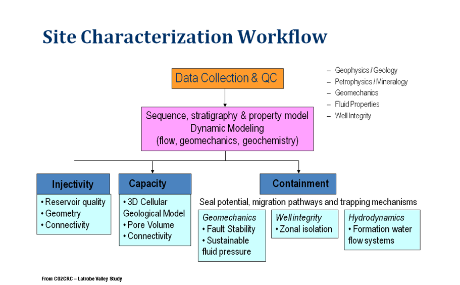
Please note that the final figure shall also include “monitorability” in addition to “injectivity”,
“capacity” and “containment”.
Page 16, Section 2.3.1
Major issues related to storage in depleted fields are not only driven by legacy wells but also
geomechanics. This should be better highlighted in this version.
Page 25, Section 2.3.4, para 2
The statement “poor permeability of the wells” needs to be revised since a well does not
have a permeability. It is the coal formation that has poor permeability. Hence, you need
multiple wells to inject CO₂ into coal formations.
Page 28, Figure 3
Figure 3 which aims at defining key terms based on the CCS Directive is very confusing. A
traditional cross section schematic would be clearer and more informative. In addition, the
purpose of leakage arrows can be questioned as site characterisation aims at selecting a
site for safe storage.
Page 30, Section 2.6
With regards to the structure of Section 2.6, Sections 2.6.3 to 2.6.14 should be placed one
hierarchy level lower than section 2.6.2, as these sections deal with fields where data can
be sourced from.
Page 31, Section 2.6.4
Hydrogeology techniques are not restricted to “shallow” formation, but can also apply to deep
saline aquifers.
Page 33, section 2.6.6, para 2
A CO₂ stream will never be 100% “pure”. We suggest to delete pure in the text.
Page 34, Section 2.6.8
Seismicity needs to be screened for, as stated in the document. However, its link to
geomechanics is different than the one suggested in this section. The definition of seismicity
needs to be reviewed.
Page 37, Section 2.6.13
A large number of competing sub surface activities compared to CCS are listed in the
document. However in most cases the other activities are not relevant in the area of the CO₂
storage site. Therefore the evaluation should be limited to the fields of relevance, at the time
that the application is made.
Page 39-43, Section 2.7.1-2.7.8 (also Fig. 2, Page 15 above)
It should be clearly distinguished between essential “must” contents and options that should
be put into place, if possible for example that a minimum availability of data is given.
The requirement for scenarios for each parameter is not useful. Only a limited number of
parameters will have significant impact on the results so that the number of relevant
scenarios to look at is much smaller, whilst still providing extensive coverage of all likely
future conditions.
Page 45, Section 2.8
Table 1 “pressure and temperature of the storage formation as a function …”
Simulation including temperature makes the dynamic modelling very difficult. Temperature
effects, however, can be estimated by using a simulation model not of the entire hydraulic
system but only of the small part in the near well bore.
As thermal effects are not necessarily required to understand the CO₂ injection behavior a
storage site specific decision has to be taken. Whether non – isothermal simulation of the
CO₂ injection site is required can be assessed using injection well monitoring data. If
potential induced temperature effects cannot be understood using isothermal simulation a
non – isothermal simulation shall be considered.
Table 1: “increased seismicity and elevation of surface …”:
Seismicity cannot be a direct output from simulation model. A further “iteration” with
geomechanical / geophysical model is required. The same applies for surface uplift.
Page 47, Section 2.8.3
Paragraph 2, point 3:
“pressure changes estimated from land surface deformation measured using satellite
imaging or tiltmeters”. There are currently no certainty that these technologies [tiltmeter,
satellite imaging] can be applied for every storage site. Furthermore pressure estimation
using surface deformation is not a good practice as surface deformation is dependent on
multiple factors, not only on reservoir pressure.
Paragraph 3: Whether 4D seismic is applicable must be separately checked for every
storage site.
Page 49, Section 2.8.3
As stated in the document, deviations between actual measurement and backcasted parameter could be “much wider” if the storage formation is complex (heterogeneity,…), which will ultimately be the case for most of the storage sites. Hence, an objective of 1% deviation between model and reality does not seem achievable.
Page 51, Section 2.9
As risk assessment is a topic extensively covered by GD1. The text in GD1 and GD2 needs to be better integrated.
Page 53-54, Section 2.9.1
When talking about build up of local and regional subsurface pressures, it is important to state that this is the case for aquifers. For depleted oil and gas fields projects are mainly (almost) restoring the original pressures to regional averages.
b. Chapter 3: Composition of CO₂ stream
From an operator point of view, flexibility is important and no additional recommendations or requirement beyond the OSPAR-ones in 3.1.1 are desirable. Any more detailed requirement/recommendation would reduce the possibility to optimise the CO₂ value chain to the local boundary conditions, both with regards to HSE and costs. For that reason, every recommendation of the text boxes should not be transformed into requirement. By setting one detailed purity requirement to be met by all CCS-projects, one could expect knock-on effect on selection of capture technology and the CCS value chain may become more expensive and less safe.
From a supplier point of view, technical solutions with feasible costs (CAPEX, OPEX) are required. Developing technical solutions to a mature status requires certain flexibility in the boundary conditions. There is already a mechanism installed in the Integrated Pollution Prevention and Control (IPPC) Directive to define Best Available Techniques (BAT), collecting all information on different types of technology enabling authorities to set permits for all plants within the scope of the IPPC. By the nature of power plants and selected CO₂ capture technology, the composition of the gas streams will vary.
The results from the CCS pilot- and demonstration plants will provide a clear definition of the CO₂ quality associated with different technologies for use in the BREF (Best Available Techniques Reference) Document for Large Combustion Plants (LCP). This is part of the defined industry consultation process under the IPPC Directive. It is important that GD2 does not supersede this established process. On the contrary, it would be useful to establish a similar process of engaging with industry on technologies not covered by the IPPC Directive.
ZEP also suggests the inclusion of a paragraph about CO₂ composition optimisation for the integrated capture, transport and storage chain. Capture, transport and storage optimisations need indeed to be assessed with respect to CO₂ specifications. Specification to satisfy specific transport or storage requirements will come at a cost for the capture facility and thus the overall chain. An example is the choice of the place where to dry the CO₂, where for specific circumstances (short distance, reservoir) the absence of an energy consuming dryer unit may outbalance the additional cost for more resistant pipe material.
Page 61, Section 3.1.1, para 5
It does not seem necessary to mention that air pollutants shall meet requirements from IPPC and LCP, because this is already covered by current EU legislation. But it is necessary to change legal requirements related to the different capture processes (ref. study from TU Hamburg-Harburg for German Environmental Agency in 2009).
Page 62, Section 3.3, para 1
There are also process limits which will not allow decreasing incidental substances. The impression that only costs are relevant as key parameter should not be given.
Page 63, Section 3.3, para 2
Clarification is needed with regards to the requirement for facilities which fall under the CCS Directive to also comply with the LCP and IPPC Directives for emissions
Water content is likely to be higher than 0.3 vol%, depending on the degree of compression and the number of condensation stages installed. Water content is therefore pressure-dependent. Directly after the capture process, the water content is 3 vol%.
Page 63, Section 3.3, para 3
“Steam reforming” is not a capture process, but part of the gasification for light hydrocarbons.
Page 64, Section 3.3, para 2
The statement according to which “pre-combustion capture can also be used for flue gases resulting from coal based gasification” is not accurate as pre-combustion capture is performed on fuel (syngas) gas rather than flue gas.
Page 67, Section 3.3, para 2 and Table3
The actual IPPC/LCP requirements for coal fired plants require a very high abatement of PM and therefore 99% is the value of capture of heavy metals in the fly ash. The document gives the wrong impression that high concentrations of heavy metal in the CO₂ stream could be reached.
In addition, together with concentrations a mass flow is required, because there great differences in the gas streams.
This illustrative Table 3 is the results of calculations. However, modelling does not provide with good results of trace components in real gas. As a lot of pilot plants are now in operation, ZEP advises to collect results from different EU projects like CESAR with the pilot plan in Esbjerg.
The Volatile Organic Compounds (VOCs) should also be mentioned in the table. It is not sufficient to only list “amines” and “glycol”.
Finally the level of nitric oxides for IGCC (11 ppmv) is incorrect. There will be no NOX in the syngas as there are no mechanisms by which nitric oxides would be formed in the gasification, acid gas cleanup or carbon capture steps. Nitrogen dioxide is formed in most combustion processes and needs air or another oxidant whereas gasification provides a reducing environment that will not promote formation of any nitric oxides. With oxygen blown IGCC, there is scant nitrogen available for oxide formation even if there was a mechanism. Also, physical sorbents such as Selexol are commonly used for both CO₂ and acid gas removal and CO₂ capture do not operate at conditions that would cause formation of nitric oxides. Therefore this entry in Table 2 should be blank.
Residual particulate matter (e.g. coal particles) will, if present, also impacts on the different units of the storage system. There will i.a. be a risk of clogging that needs to be investigated in relation to pore size of storage structure.
Page 69, Section 3.4, Table 4
There is no basis for expecting H2 embrittlement at the temperatures, partial pressures and concentrations that will be encountered in CO₂ pipeline conditions. Mentioning it could raise unnecessary concerns. Carbon steel which would typically be used in CO₂ pipelines is a standard method of transport of hydrogen in cylinders typically at 2000 psia. An applicable reference is the API Recommended Practice, 6th edition, Steels for Hydrogen Service at Elevated Temperatures and Pressures in Petroleum Refineries and Petrochemical Plants, 2004. Figure 1 from that document (Nelson Curve) shows carbon steel applicable to 450 °F at 2200 psia while maximum temperatures in pipelines will be a fraction of this temperature limit. Ammoniac (NH3) should be added to the list and VOCs should be mentioned – instead of amines and glycol.
Page 70, Section 3.5.1, para 3
The most important aspect of water concentration is not mentioned: water concentration limit is closely related to the material philosophy. It is not always necessary to avoid free water (or proton donating component). A good example is at Sleipner where Statoil uses stainless steel and relies only on knock-out drums. The margin to formation of free water is low but does not pose any threat.
Page 70, Section 3.5.1, „H2O concentration limits“ (Line 5):
Pipeline temperature is normally 8 – 12°C (or even lower offshore)
To operate a pipeline with 31 ° C would require an isolation and heating. The transport is normally carried out in liquid form, not in the dense phase. (At Sleipner and In Salah, the transportation is carried out in dense phase).
Page 71, Section 3.5.1, para 5
O2 in CO₂ can lead to heating of the oil reservoir but this does not pose any threat if proper knowledge, design and operation are applied. Air injection with 21% O2 (or in situ combustion) is a known process in oil and gas industry, and has been even studied for the North Sea on Ekofisk (SPE97481). Moreover, produced water is sometimes reinjected into the oil reservoir with some dissolved oxygen. This does not mean there is no uncertainty, especially for operator without such experience. ZEP’s opinion is that the number of 10ppm O2 lacks experimental and theoretical evidence and should therefore be used with caution.
Page 72, Section 3.5.2, para 4
The amount of 4-5% non-condensables is only valid for Enhance Oil Recovery (EOR) cases where operating above a minimum miscibility pressure (MMP) is desirable. Noncondensables increase this MMP. Although, it is expected that the amount of noncondensables will be in most cases well below 4-5% due to increased compression and transport costs, a case where 10% N2 or CH4 is the economic optimum should not be made impossible with a requirement of <4-5% non-condensables.
Page 75, Section 3.6, Table 7
The unit ppmv is missing in Table 7.
Page 77, Section 3.7.1, text box
Suggesting a lower limit for H2S in comparison to CO₂ pipeline standard in the USA is overly restrictive and could add considerable costs if adopted as a standard in the EU. We note that 10ppm derives from natural CO₂ sources which are as-is versus a safety based standard acceptable for permitting by pipeline companies such as Kinder-Morgan or Denbury.
Page 79, Section 3.7.2, para 2
“Both the IPPC Directive and the IPPC Directive” should be replaced by: “Both the IPCC Directive and the LCP Directive”
Page 81, Section 3.8
Figure 4 adds value to the understanding and should be introduced earlier as in the summary.
c. Chapter 4 : Monitoring
Page 89, Section 4.2.1, para 1
Though the document states that transport emissions are outside the scope of this work, there is a section on pipeline monitoring (page 100).
Page 92, Figure 5
Figure 5 comes across as an over prescriptive list of elements to be included in a monitoring programme, especially around plume monitoring. It may be very difficult to obtain some elements allowing an evaluation of trapping mechanism and trapping efficiency without a dedicated monitoring well drilled down to the formation. The benefit of such monitoring well to ensure safe storage should be assessed by the operator and the CA and weighted against potential risk of puncturing the seal. Establishing such monitoring well should only be decided when clear benefits are foreseen.
Page 95, Section 4.3.1, Table 11
Care needs to be used when discussing the use of individual technologies. Figure 11 is a list of possible MMV technologies determined by ICF. This is only one institution’s view and should not be used as a checklist for regulators. There are technologies on the list which are not suitable for commercial scale projects e.g. eddy covariance. In addition, the success of seismic at Weyburn and Sleipner has been quoted as a good method of quantification of the CO₂ plume. While it is stated in GD2 that seismic will not work at all sites (Sleipner has indeed a near perfect conditions for the technique), it is not recognised that the technique gives only semi-quantitative estimates of plume volume and cannot be repeated at the same frequency at all storage sites. Sleipner and Weyburn projects used seismic as a research tool, and it would not be practical or cost effective to expect commercially viable projects to copy the same use of seismic. In addition, ZEP would question the status (primary; secondary or potential) associated to each technology.
It seems also unclear whether monitoring techniques are mandatory or only “suggested” by the document. For example, monitoring if the reservoir pressure is exceeding the fracture gradient for the caprock should be a mandatory requirement. This appears mandatory on page 104, but not on page 101. The discussion around baseline activities is similar (page 105). Baseline surveys are necessary.
Page 103, Section 4.4.3, para 4
It should be highlighted that compositional sampling in wells is not a continuous measurement in reservoirs. It can only be achieved in shallow aquifers.
Page 104, Section 4.4.7th bullet
This implies the need for quantitative 3D saturation models. Even where seismic is an appropriate technique it will only give semi-qualitative results. In addition point source petrophysical measures are spatially restricted to the near-well bore area and are again semi-quantitative
Page 104, Section 4.4.8th bullet
This statement appears to require the repeated use of 3D seismic as well. 3D seismic can achieve such result. A combination of geodetic (i.e. InSAR technology) and/or specialised geophysical techniques might help better achieve this aim.
Page 110, Section 4.4.6
As some relations between CCS and EU ETS Directive are investigated, it would be useful to have a brief reminder on the EU ETS Directive.
Page 117-119, Section 4.5.7 Accounting for emissions (including leakage)
GD2 links the accounting for emissions and leakage to the EU ETS Monitoring and Reporting Guidelines. ZEP’s view is that definition and verification of monitoring shall remain the responsibility of the CA, according to the subsidiary principle. This will ensure the quality of the assessment and give legal certainty to CCS companies.
GD2 proposes to quantify emissions on leakage rates measured in t/d or t/h. The units t
CO₂/h and t CO₂/d do not reflect the expected leakage behaviour of CO₂ storages and the experience gained in global storage projects (e.g. Sleipner, K12B, Ketzin, Frio). GD2 suggests very high and unrealistic emission rates.
With regard to natural CO₂ emissions the leakage rate should be given in t/annum. Seasonal variations in the natural CO₂ flux reach orders of magnitude and need to be taken into account.
Today, there is no measurement technique able to provide a full quantitative analysis of CO₂ leakage from a surface from the size of an underground CO₂ pressure plume. Therefore, no specific measurement methods should be solidly defined by law or regulation. Instead of that, a site specific range of monitoring techniques which deliver CO₂ emission data (based on best available technology) in the unlikely event of a leakage needs to be set up.
According to GD2, the amount of emissions leaked from the storage complex shall be quantified with an uncertainty of 7.5% for the quantification of the emission amount in the event of leakage. This contradicts the results obtained by a number of research projects incl. the EU projects GESTCO and GeoCapacity.
They investigated possible CO₂ storage facilities in up to 19 EU countries. These projects have shown that, after careful analysis of all facts, safe CO₂ storage facilities can be erected at many of the sites under review. Information on imponderables that would justify an uncertainty of 7.5% was not found. Pursuant to Article 13 of the CCS Directive, the national authorising authority ensures via appraisal and permitting of the monitoring plan that the monitoring is based on the state of the art and involves minimum imponderables. The procedure proposed in GD2 seems to contradict some of provisions included in the
Article 13 of the CCS Directive.
d. Chapter 5 : Corrective Measures
ZEP would suggest rewriting the whole chapter 5 on corrective measures with a particular focus on corrective measures relevant to (i) incidents for which solutions are already available, (ii) accidents needing extra action to minimise surface impacts, and (iii) unforeseen Force Majeure events for which contingency plans need to be activated. For each of those sub-cases, a detailed list of technologies available should be referred to, together with cost ranges and remediation potential. This would highlight the analogous and applicable disaster prevention plans that are required for the oil and gas industry.
Page 126, Section 5.3, para 3
Although there is “not much practical experience with use of corrective measures in geological storage of CO₂”, it should be highlighted that there is a lot of experience with well integrity corrections (which use similar technology).
Guidance Document 3
Criteria for Transfer of Responsibility to the Competent Authority
Introduction
The CCS Directive and associated guidance documents have been written with mature, commercial-scale CCS in mind. However, in order to ensure investments of critical demonstration projects, ZEP believes it is important to promote a pragmatic approach and allow Member States and Competent Authorities to be flexible in their implementation of the CCS Directive. EU CCS demonstration projects will be critical in providing greater clarity on the technical and legal requirements of CCS projects.
ZEP would like to recommend that the guidance document promotes industry best practice in managing risk and uncertainty. It is therefore important to bear in mind the applicable precedents which already exist in the oil and gas industry – in particular, experience of: sub-surface modelling, CO₂ injection, site abandonment and monitoring.
A key concern for ZEP is that GD3 should emphasise the use of a criteria-based approach, as opposed to a time-based approach, for determining when hand-over can take place. Only a criteria-based approach can provide the required certainty for the competent authority and an additional time-based approach would not add further value.
This GD should always cite the relevant paragraphs of Article 18 of the CCS Directive when referring to this Article. This would improve the traceability of GD3.
Specific comments
Page 5, Section 2, 2nd bullet and Page 15, Section 3.3, para 2
The CCS Directive and guidance document do not give certainty to the operator on the question of when hand-over can be expected to occur. The guidance document emphasises a minimum time period of 20 years post-closure before hand-over can take place. ZEP has strong reservations on the narrow use of a time-based approach for handover and believes that only a criteria-based approach is much more relevant and can give the required certainty to the CA that hand-over can take place.
ZEP suggests that GD3 emphasises the use of criteria-based hand-over and encourages MS to avoid the use of a time-based approach. The CCS Directive includes an objective description of the conditions for hand-over after the 20 years period. Before the 20 years period, however, the Directive stipulates that the CA needs “to be convinced” that the conditions are fulfilled. ZEP would like to see clearly stated in GD3 that when the handover criteria are fulfilled, the operator has the right to transfer the storage site to the CA and the CA cannot refuse such hand-over.
In other words, when the CA is satisfied by the achievement of criteria for transfer, the CA should not unnecessarily withhold or postpone the transfer decision. GD3 should outline the possibility for MS to establish, on a case-by-case basis, specific criteria for transfer as a part of the storage permission.
The CCS Directive and the current guidance document do not provide enough clarity on when transfer can be handed over. Operators cannot take on indefinite risk. Deployment of CCS will require that the criteria for hand-over of each project should be individually agreed prior to the start of injection and not changed for a given project. These need to be achievable and objectively measurable. Deployment of CCS would be supported significantly by a maximum rather than a minimum post closure / pre transfer period.
This maximum period could also be shortened as experience from CCS projects is gained.
Please also see comment on Section 3.1.2 below.
Page 5, Section 2, 4th bullet and Page 15, Section 3.2, last bullet
ZEP believes that the CA should be as flexible as possible on the condition to remove all facilities (e.g. must seal injection wells but platform, pipeline, etc can remain). Decommissioning can indeed take a long time and cost savings may be possible if operators are given time to seek synergies with the decommissioning of neighbouring facilities. ZEP suggests that GD3 defines injection facilities in a way that allow such sequential decommissioning to take place.
Fundamentally, decommissioning does not have any link to the storage integrity of the reservoir. Also, the Financial Security in place to cover the cost of decommissioning should allow the CA to provide this flexibility. This would also give the operator the opportunity to seek synergies with the decommissioning of neighbouring facilities.
Page 6, Section 3, 1st para
“This draft decision will include details on the method that is to be used for determining that the site has been sealed and for the removal of injection facilities”
The current wording of GD3 may be interpreted as the CA prescribing a methodology whereas the appropriate and less onerous action for the CA is to approve (or disapprove) the methodology proposed by the operator.
ZEP considers the following wording more appropriate:
“This draft decision will include an approval of the method that is to be used for determining that the site has been sealed and for the removal of injection facilities”
This would clarify that the specification of the method in the draft decision is also accomplished, if the draft decision approves a method suggested by the operator. It would help to interpret the wording of Art. 18 (3) sentence 2 (“The draft decision shall specify the method for determining that the conditions referred to in paragraph 1 (a) have been met…).
Page 7, Section 3.1.1
“Hence, it is important to recognise that assessing the conformity of models for geological storage is an emerging area of science and practice.”
The use of modelling to project sub-surface behaviour of substances/structures is well established and advanced in the oil and gas industry. This experience also includes a significant number (thousands) of CO₂ injection activities.
The predictive power of models increases over the operating history of a specific site, and models can be expected to have developed to a great degree of accuracy postclosure of the site. It is important to note that depleted oil and gas fields already provide well developed models based on the production phase; changes to the models of such fields are likely to be very limited.
It must be remembered that models are forecasts and that a number of scenarios may show conformity with the model. For this reason, and to increase certainty, multiple models should be used and hand-over determined by demonstrating that models leading to non-containment of CO₂ can be rejected with confidence. Such a criteria based hand-over is recommended over any time-based approach.
It should also be noted that experience exists for wells being drilled into high-CO₂ concentration reservoirs. Many of these are abandoned soon after when CO₂ concentrations become too high for economic recovery of the gas. Standard abandonment procedures, as prescribed by existing regulation, (for corrosive, high pressure abandonment) are used. Complete abandonment follows demonstration that the cement plugs hold pressure. This includes restoration of the site which then can be used again for other activities (including housing).
Page 7, Section 3.1.1, para 3 and Page 8, Section 3.1.1, last para
The guidance document does not provide guidance on the frequency of model calibration nor degree of deviation observed in actual behaviour that would require re-calibration. Conformity between the model and actual behaviour is similarly not defined.
ZEP understands that it is difficult to be prescriptive due to the great variation in site characteristics, multiple options for CO₂ injection and applicability of monitoring methodologies. However, operators should be given a certain degree of certainty that at the time of hand-over, modelling and recalibration carried out over the life time of the project will be sufficient to determine that the transfer criteria have been met.
As a solution, GD3 should stipulates that the methodology used in modelling should be approved by the CA at the award of storage permit and that recalibration or change in methodology should take place on recommendation of the operator and subsequent approval by the CA. Additionally operators could be obligated to report observed deviance from models as part of regular reporting.
This Section in particular but also the whole GD3 in general lacks a clear definition of what “significant deviation” is supposed to mean.
Page 7, Section 3.1.1, end
“The geochemistry of the rocks, along with monitoring evidence during the post-closure period should indicate that there is little to no risk for well integrity being compromised in the future.”
The term “little to no risk” requires further qualification.
Page 7, Section 3.1.1, end and Page 11, Section 3.1.2, last bullet of list and Page 13, Section 3.2, table 1
Before transfer it is recommended that the CA gets data on the chemical composition of fluids in the reservoir and caprock. While it is relatively easy to collect a reservoir sample, the collection of new caprock samples could compromise the integrity of the container. Unless there is an existing dedicated monitoring well placed in the cap, it will be difficult, expensive. Besides, there is a risk of compromising containment security just prior to transfer to get this data. A more realistic alternative is to resample fluid and gas compositions from the overburden formations after the defined container complex. However, this is also influenced by the availability of a monitoring well which is capable of allowing PVT quality geochemical sampling from it.
Maintaining access to storage reservoirs and wells for monitoring pressure and geochemical changes in the storage complex constitutes very high additional costs, especially for offshore CO₂ storage. The necessity of any additional well should be determined on a case by case basis.
Page 8, para 4 and 5
The CA and the operator should both have confidence in the results of the modeling. However the wording “The CA should be confident that the model is indeed the best one …” (3.1.1., page 8) could be misinterpreted. The operator should be free to choose a model, provided that it is demonstrably fit for purpose for the task to be undertaken.
Evaluating the quality of a model is not possible looking on a single value of deviation between model and monitoring results. Different models will most probably match different parameters more accurately.
Is a model that matches the pressure values by 10% and flow data by 7 % better than a the model that matches the flow data by 10% and the pressure values by 7%, or another which matches pressure and flow to within 2% but over-predicts the concentration of a minor, inert, contaminant by 50%?
Page 9
“Conformity of the model simulations to observed behavior may be defined as – point a) “ For at least five years before the transfer, the model does not need any recalibration of the geological characteristics.
CO₂ placement may be very difficult to predict locally (as demonstrated by field cases in Europe). To model CO₂ front movements, it may hence be required to update locally models (to match a CO₂ detection in a given observation well for example). This should not be considered as a model unconformity.
Page 10
The documentation of how site performance evolved relative to the predictions should most importantly include “the chemical composition and structure of fluids and rocks in the storage complex (4)”.
Change of rock structure in a storage site may be impossible to assess due to rock heterogeneities. Even if it was possible to core in a place that was flooded by CO₂, difference of mineralogy (with a reference sample) and uncertainties in the kinetics of the rock alteration (depending on pressure and temperature conditions) will make very difficult to assess any rock structure evolution.
The documentation of how site performance evolved relative to the predictions should most importantly include “active processes such as dissolution, density currents, and mineralisation (5)”.
See above the comments regarding dissolution and mineralisation. Monitoring technique able to identify density currents are yet to be designed as the density difference between CO₂ saturated brine and the original formation brine may be minor. This has never been fully monitored anywhere in the world due to the fact that dissolution is a very slow process, on a long time-scale.
Regarding mechanical integrity test of abandoned wells: How is it expected to test mechanical integrity of abandoned wells with no more access to the well itself? Does this mechanical testing prohibit abandoning wells?
Page 10, Section 3.1.2
The guidance document does not address the eventuality that a leakage has occurred and corrective action has been taken. The current wording may preclude transfer in such instances, irrespectively of the robustness of the corrective actions taken. There should not be any 10 year period (or more) as indicated if corrective and robust actions have been taken.
This uncertainty extends to the application of a minimum of 20 years post-closure period before hand-over can take place. If a leakage occurs and corrective actions have been taken, the 20 year minimum time period should not be affected. ZEP strongly supports the use of a criteria-based approach for determining hand-over. Such an approach would remove this issue.
In both the above cases, surely the nature of any incident and the corrective actions undertaken should be evaluated before any decision is taken on the effect on hand-over criteria.
Page 10, Section 3.1.2 and page 13, Table 1
In this chapter GD3 does not define a period of time in the past in which there should be no detectable leakages. On the contrary, the Table 1 – Requirements in a Transfer Report on Page 13- refers in this context to a continuous 10 year period or more. More consistency between the different articles would be welcomed.
Page 10-11, Section 3.1.2, list
GD3 should stress that projects are unlikely to use each of the methods described in the illustrative list. A project will rather monitor the CO₂ stored by using the most appropriate techniques with regards to the specific characteristics of the reservoir.
On pressure data:
It is only possible to obtain actual pressure data from discreet points in wells, the rest will be extrapolated or integrated with geomechanical and / or geodic data depending on the geological setting of the storage complex.
Pressure may change in the complex due to other usage (pumping water for agricultural usage for example), which would not provide any relevance for the storage site itself. Pressure may take a long time to stabilise in the storage site, and difference (between model and observations) should be considered to the trend and not to the expected stable value. In some depleted gas reservoirs, pressures for example are not expected to stabilize before 200 years. Note also that a pressure decline faster than the one expected at the end of the injection period could be a positive indication.
On seismic surveys:
Seismic surveys are of little use for storage in certain gas fields; any leakage will be very slow (when underpressure in reservoir) and minor; therefore it cannot result in detectable volumes of leaked CO₂ in the short-term (hundreds of years).
Page 11, Section 3.1.3
Requirements b) and c) may be very difficult to meet within a reasonable timeframe as modeling may indicate that future stable values will only be reached after a significant time period.
For wells in depleted oil and gas fields there will not be a “stable end-state” for a significant number of years as reservoir pressures are expected to increase very slowly to the pressures that are normal at the reservoir depth (in most cases). Current practice accounts for these changes and ensures that safe abandonment can take place despite these ongoing, albeit very slow, changes.
It is recommended that new procedures for oil/gas field abandonment are not legislated. Instead current procedures should be extended to account for the increased assurance needed for CO₂-storage reservoirs to demonstrate containment for emission accounting purposes.
The guidance document would benefit from defining “evolution towards long term stability” as monitored parameters following a similar trajectory to that which has been modeled.
Page 12
The first sentence: “The stable… at the storage complex” is unclear and should be rewritten.
“It allows for Migration Assisted Storage (MAS) trapping, as the CO₂ plume can indeed be migrating horizontally or laterally at slow rates (less than a millimeter to meters per year …)” Migration may occur by gravity at a rate of 100+ meters per year for a 1% dip aquifer.
Thus it seems that the term “meters” is not really appropriate.
Page 12, Section 3.1.3, box and Page 13, Section 3.1.3, 2nd para
It is correct to highlight that stability does not preclude movement of CO₂ in the subsurface. The concept of a storage complex evolving towards long term stability is an important balance to a potentially narrow definition of the CCS Directive in order to demonstrate that “all available evidence indicates that the stored CO₂ will be completely and permanently contained”.
Page 13, table 1
Absence of any detectible leakage; the project proponent should, at minimum, be given the chance to remedy any such leakage in a reasonable amount of time (but promptly), but should not be penalised for any single leakage event in a continuous 10-year demonstration. The proponent should have the opportunity to show good faith and be able to remedy such leaks promptly.
Page 16, box
“However, the CA could require certain monitoring facilities to be maintained beyond the transfer, in order to continue monitoring beyond transfer or for other nearby storage sites”.
Please confirm and include in the document that the transfer will be accompanied by appropriate and mutually agreed property transfer of storage site, storage complex and selected facilities. This is not mentioned and could be necessary if monitoring continues after transfer to CA. It should also be stated that the CA is responsible for the performance of monitoring activities post transfer of responsibility.
Page 16, Section 3.6
ZEP agrees with a requirement to hand-over raw data. Models are proprietary and will not be handed over.
If any interpretations would be required to be handed over, MS and CA must provide a guarantee that commercial confidentiality will be assured.
Page 17, last paragraph
“Beyond the transfer, the CA may not recover any costs from the operator unless there are leakages or significant irregularities as a result of operator’s negligence, concealment of data, willful deceit or failure to exercise due diligence”.
This guidance document should have provisions specifying under which conditions the MS can re-open the operator’s liability after transfer of responsibility, with particular focus on how the “concept of fault or negligence” should be construed. The way the fault provision is worded in the CCS Directive could give the authorities a wide discretion to re-open liability after transfer. For example the list of examples given for what could constitute a fault is a very “mixed bag” and it is not clear whether there has to be a causal connection between a specific fault and the relevant harm which becomes manifest after transfer. MS and CA (i) award licenses to storage sites; (ii) approve impact assessment studies and (iii) give the necessary permits. Any re-opening of liability after hand-over should take into consideration the role the MS and CA during the process.
ZEP is only pin pointing this as an issue and has unfortunately not been able to come up with a proper suggestion on how to solve this issue. ZEP is willing to engage in a continuous dialogue with the European Commission and EU Member States to try to come up with future solutions.
Guidance Document 4
Article 19 Financial Security and Article 20 Financial Contribution
Introduction
ZEP welcomes the review and consideration of a wide range of possible Financial Security (“FS”) and Financial Contribution (“FC”) mechanisms in GD4. However the guidance document does not suggest solutions to solve the ambiguities of the CCS Directive in terms of the security mechanism and actually proposes some mechanisms that would increase uncertainty for operators.
In order for CCS to become commercially viable, the industry needs a strong framework and a manageable risk exposure. Unnecessary costs imposed on the storage operator could constitute a show-stopper for the deployment of CCS in Europe, yet it has the potential to contribute significantly to the mitigation of climate change. Unlimited exposure, in particular, to an increase in CO₂ allowance prices will discourage operators from undertaking CCS projects and be counter-productive from a climate risk mitigation point of view.
GD4 considers only FS and FC; the operator’s liability, which is a larger topic, is not specifically addressed. ZEP recommends liability to be explicitly included and addressed since this is a potential risk for the operator.
ZEP supports the fact that FS and liability provisions should remain an incentive to act as a prudent and reasonable operator and develop the best and safest storage sites. However, GD4 imposes unbearable uncertainties and risks on the storage operator. It would be neither appropriate nor economically feasible for a storage operator to establish any CO₂ storage site with maximum scale of liability inferred by the current document. The guidance document should therefore highlight issues that Members States will need to resolve in national legislations and regulations to be enacted.
GD4 fails to present a convincing solution as to how to deal with the theoretical risk of leakage and the ensuing requirement to surrender allowances. Indeed, it is not possible for an operator to finance a security for surrendering allowances needed to cover all of the stored CO₂. Whereas potential damages to third parties can be insured, the obligation to surrender allowances in case of leakage is a core entrepreneurial risk and is not insurable. It is also not possible to finance such a security through other generic FS instruments, except if the Member States share the risks, for instance, by acting as an insurer.
A key prerequisite for CCS activities is the possibility for operators to hand-over their liabilities at some stage to the CA, as commercial companies cannot operate over an indefinite horizon. The CCS Directive explicitly forecasts a hand-over mechanism. However, Article 20 of the Directive is ambiguous on the scope of the FC post hand-over. GD4 (Section 3, p. 42) echoes this ambiguity. It should instead make it clear that (i) the operator liability and corresponding FC is limited to monitoring costs over a defined period and that (ii) operators have no other liability post “hand-over”. If not, any hand-over concept would have no meaning.
GD4 echoes the Directive’s indication (Article 19.2) that the FS should be adjusted to reflect changes to the assessed risks and obligations. Few, if any, commercial operators will be able to take unlimited risks and be subjected at any time to changes in FS or FC requirements from the CA.
Obligations of an operator who is a member of a Group of companies, with good financial capacity (e.g. rating greater than or equivalent to A- with Standard and Poors), can be covered via a parent company guarantee from an appropriate company in their Group (which may be waived by the CA for those members of a Group of companies with an excellent financial capacity, e.g. rating greater than or equivalent to AA-), or adequate insurance/bank guarantees. An operator who is a member of a Group of companies with a lower financial capacity could secure their obligations via a combination of any of the following: insurance, bank guarantee / letter of credit, from institutions with sufficient financial standing (e.g. credit rating equal or above to A-) and /or cash deposits.
ZEP emphasises that, as implied by GD4, no single blanket security mechanism should be applied. GD4 could indicate even more clearly that the most efficient solution to the deployment of CCS is a combination of tools, to be applied according to operators’ financial capacities.
Specific comments
Page 4-5, Section 2.2, (a) i. first three bullet point
The description of “pre-funded” mechanisms (deposits, irrevocable trust and escrow) should make clear that these mechanisms do not eliminate risks for the CA since they include an underlying significant risk on control of the funds pre-advanced. Such preadvanced funds (i) could be mismanaged and (ii) will be exposed to the credit worthiness of the entity holding the funds. It should not be assumed that financial institutions are necessarily safer options than companies for guaranteeing or managing FS.
Page 5, Section 2.2 (a) i.
The list of potential complementary instruments should include all various FS securities reviewed later in the document including self assurance based on annual financial test.
Page 6-7, Section 2.2, (a) i bullet points 4 to 6 and final paragraph
The description of bank guarantee, letter of credit and surety bonds and insurance should make clear that the value of these instruments will depend on the credit worthiness of the issuing institutions that could be lower than that of certain operators. Insurance options described in this paragraph should include insurance affiliates of operators being members of a Group of companies when such are established.
Page 8, Section 2.2, (a) ii.
The key criteria for assessing FS should include:
- Cost of the proposed option for the industry (should be limited to the requirement under the CCS Directive to avoid unnecessary costs)
- Simplicity in administering the scheme,
- Recognition of operators potentially greatly varying credit standing – Risks/control issues associated with the proposed mechanism.
Insurances can also play an important role: It would e.g. be preferable to use existing, established and experienced liability insurances as one FS instrument (as a combination and mixture of multiple FS instruments) for some obligations like damages to human health, buildings, other property damages and damages to the environment (ELD-Directive 2004/35/EC). The good experiences made with the implementation of the ELD in the existing and established liability insurance system could be used:
Obligations resulting from environmental liabilities under Directive 2004/35/EC (ELD) are also insurable. To compare the CCS-Directive with the ELD-Directive and the implementation e.g. in the German private public liability insurance system there is established an effective FS instrument which is also experienced to compensate claims in practice.
Page 8, Section 2.2, (b)
Under options for “any other equivalent”, a mutual guarantee system among operators could be added as an option to be considered. ZEP recommends nevertheless that such mutual guarantee system is not made mandatory.
Page 9-11, Section 2.3(a)(ii) and (iii)
GD4 would benefit from clarifying some of the ambiguities or reducing some of the uncertainties existing in the CCS Directive. Article 16.5 of the Directive underlines that the CA may take corrective measures itself and recover the costs from the operator, including by drawing on the FS. However, the Directive does not specify the amount of the costs the CA may charge to the operator. This unlimited exposure will make it very difficult for any commercial company to participate to a CCS scheme. ZEP proposes therefore to clarify criteria and procedures upfront between the operator and the CA.
Similarly the obligation to surrender emissions allowance is a very significant uncertainty for the operator as the evolution of CO₂ prices is unknown. Whilst ZEP emphasises that the operator should have some liability exposures, the significant uncertainties mentioned above need to be resolved.
Page 11, Section 2.3 (a) (v)
Article 11 of the Directive indicates that the CA will take over all obligations subsequent to withdrawal of a permit. It suggests that the CA may choose to continue to operate the site and shall recover any costs incurred from the former operator, including by drawing on the FS. The provision is unclear on two particular points: (i) it does not put a time limit during which the CA could take over and operate at the cost of the operator and (ii) it does not clarify the amount the operator has to commit.
After withdrawal of a permit the CA should have the availability to call upon the FS for:
- liabilities that arose prior to the withdrawal
- originally anticipated monitoring
- closure costs up to the cap of the FS
ZEP believes that the former operator should however not be liable for any continued injection expenses post withdrawal.
Page 13, Section 2.4 (b)
ZEP believes that risk assessment needs to be managed on a case by case basis. The adequate level of contingency cannot be stated in absolute terms but should rather be the result of a structured risk assessment of the project (this risk assessment would result in different projects requiring different level of contingencies). ZEP believes it should be possible for amounts to be adjusted by multiplying with an estimated probability to calculate an expected value. The project operator needs to demonstrate the potential scenarios and probabilities of occurrence to the CA and both should agree on the appropriate probability to use. A contingency value could be negotiated to cover any additional margin of uncertainty.
Page 13-14
GD4 indicates that expected value techniques should be avoided to determine the amount of FS to be provided. These however are commonly used for uncertain / contingent liabilities. Requesting the FS to cover a worst case scenario will be an onerous requirement on the operator that would prevent the deployment of the CCS industry.
Probabilistic risk assessment is commonly used by both Industry and Governments as a practical/reasonable way to allocate scarce resources to tackle risks where most appropriate without which human activities would be severely constrained. Whilst there may be at this stage of the CCS industry less quantitative historical risk evaluation data than in other industries, this needs to be taken into account in the Probabilistic calculations and contingencies applied, rather than be ignored altogether. Analogues from similar activities can also be used.
GD4 indicates that the full cost of all possible obligations must be supplemented by a margin of at least 25%, in case the obligations were underestimated. In addition, the CA should add provisions for overheads and other administrative costs. This is likely to worsen an unreasonable burden. As a detailed evaluation of the risks has to be done it would be inappropriate to require a contingency of 25 % to cover uncertainties. Arguably, the exposure represented by FS would add significantly costs to the storage project and the actual cost of providing the FS would be a significant fraction of the overall cost of the project.
Page 15, Section 2.4 c) i.
As commented earlier on Section 2.3 (a), ZEP believes that the amount of security to cover exposure in case of withdrawal of the storage permit should be limited to any pre withdrawal liabilities (remediation, surrender of allowance on a risked basis), closure cost and monitoring cost and then be capped. In the post closure period, the amount should be reduced to monitoring costs and FS should cover possible leakage of already injected CO₂ solely. It should not cover continued injection which should be performed by the CA/ another operator upon default of the original operator. The CA/new operator will then take on the leakage risk (and the FS should be reduced accordingly) as they will have interfered with the site.
Page 17, Section 2.4 c) i.
Ability to transfer at some point responsibility of the site to the CA is a critical condition of CCS development as commercial companies cannot operate over an unlimited period of time. It is important thus that the criteria for hand-over are: (i) established prior to start of injection, (ii) objectively measurable and (iii) realistically achievable. Proper definition of the criteria, as well as capping of the post closure monitoring period in time, should be agreed prior to final investment decision. The amount of FS to be provided should take into account that cap and be reduced when closure is executed (and remaining number of year of monitoring decreases). On the contrary to the GD proposal, operators should be able to use reasonable and transparent probabilistic risk assessment of monitoring costs where appropriate.
Page 18-19, Section 2.4 c) ii
Operators should be able to determine whether corrective measures will be needed (and how often) and they should be able to have a transparent probabilistic assessment of potential corrective measures costs.
Page 19-20, Section 2.4 c) iii.
Amount of FS should be based on site characterisation and a probabilistic risk assessment. Ongoing updates of the FS according to emission allowances prices without any cap on both price and allowances would be a very onerous requirement on operators. The uncertainty and open exposure is likely to be unacceptable for most of the operators.
A reasonable compromise is to have both the operator and the CA authority to share CCS liabilities. This may also reduce the cost of the necessary FS and FC that otherwise had to be provided for the operator.
Such arrangement should be dealt with and agreed between the operator and CA before final investment decision is made. By sharing or capping liability the MS takes on the residual liability.
The GD gives a very high and unrealistic best case leakage rate of 1%. This value sourced from the IPCC special report is the worst-case scenario. It should be noted that the bestcase scenario is in fact 0%.
Page 20, Section 2.4 c) iv.
Similar comments as above apply. The estimate of closure costs underlying the FS requirements should be set and frozen prior to final investment decision.
Page 21, Section 2.4 c) v.
As per above, operators should only be accountable for liabilities arising pre withdrawal of a permit (including costs of monitoring and closure as these activities are consequences to the pre withdrawal injection activities). Operators should however not be liable for the CA decision to pursue injection as they have no control over the activities the CA would be undertaking. Injection in particular is a discretionary activity compared to monitoring what has already been injected. Thus the amount of FS security required should not cover any ongoing injection costs. If operators would have to reimburse the CA for its costs of continued injection operations, this obligation and corresponding security amount should be net of any injection revenues and need to be capped otherwise effectively the CA has an unlimited call on the former operator’s resources. By continuing injection the CA effectively takes over any leakage liabilities, as it would have interfered with the site.
Page 21, Section 2.4 c) v.
The Guidance Document could clarify how the liabilities and securities would be managed in case the storage site is operated by a consortium. Each of the co-operator registered on the storage permit should be liable and provide security proportionally to its participation interest in the storage.
Page 23-25, Section 2.4 e)
As per the above, periodic adjustments of the FS would result in a very large uncertainty for operators. GD4 should recommend the establishment of an upfront cap prior to starting of injection that will include contingencies for evolutions of prices/costs.
Page 24, Section 2.4 e)
The risk of leakage is not a direct linear function of volume injected. The amount of security required to cover purchase of allowances in case of leakage should therefore not be a direct reflection of the volume injected.
It is reasonable to adjust the FS based on scientifically sound criteria, including amount of CO₂ stored, changes in risks and in leakage pathways, new monitoring data etc. The key issue is the frequency and level of details needed for demonstrating the need to adjust. Since monitoring plans are required by the CCS Directive to be updated every five years, being able to adjust the amount of the FS every five years would be prudent and efficient. More detailed principles for later adjustment of FS must be agreed between the operator and the CA before FID. Such principles should also take into consideration that operators are not able to take unlimited risks and be exposed to any changes in FS and FC.
Page 25-35, Section 2.5/ Section 2.6
It would be clearer to merge the section about criteria for operators and issuers as both need to be considered in the summary of potential strength and weaknesses of generic FS instruments (table 3). Note that these sections 2.5 and 2.6 also include a number of repetitions with section 2.2 and the three could be grouped.
Page 27-28, Section 2.5 Table 3 #1, #2 and #3
Deposits/ Trust/ Escrow. It should be flagged that these are very costly options for the operators (cash mobilisation) and for the CA (administration of fund). The risk of mismanagement of funds and counterpart risks on financial institution or Trustee holding funds on behalf of the CA should also be flagged. These options will require time and efforts for administration including management of internal controls exposure.
Page 28, Section 2.5, table 3 #4
Bank Guarantees is less costly to the industry than previous option and it is also easier to manage for the CA (only need to monitor credit standing of the Bank/financial institution issuing the guarantee, plus monitoring guarantee expiry dates). Bank guarantees imply no internal controls exposure. As mentioned in the table quality of the security depends on financial strength of the issuing institution which may or may not be better than the one of certain operators. A minimum credit rating threshold could be defined. It should be considered that institutions should have a credit rating equal or above to A- with Standard and Poors.
Page 28-29, Section 2.5, table 3 # 5 and #6
Insurance.
Slightly more difficult to administer as detailed policy terms need to be reviewed but overall simple. As mentioned for bank guarantees, the quality of the security depends on financial strength of issuing institution which may or may not be better than that of certain operators. A minimum credit rating threshold could be defined. We would suggest institutions should have a credit rating equal or above to A- with Standard and Poors.
Currently there is no comprehensive long term insurance policy offered by anyone. GD4 reflects this correctly. The only viable insurance product (from the insurance industry’s perspective) is a 1 or 2-year term policy that needs to be renewed. The policy is typically very narrowly focused with very high “deductible”. This reflects the continuing reluctance and conservatism of the insurance and re-insurance industry to cover CCS projects based on the still-uncertain long term risks that they believe will continue to exist. Until more operational data and experience is collected, the insurers and re-insurers will continue to believe they have no way of calculating this long term risk and thus very little scope for designing any insurance policy beyond a 1 to 2-year revolving term.
There is no need to establish new organisation via special arrangements for compulsory insurance solutions which depends on additional administrative measures and high costs. Experiences with other EC Directives demonstrate – also for a long term period – that public & private liability solutions (and not compulsory insurances) are an effective FS instrument to compensate third party liability claims obligations.
We note that an option not provided by the GD4 is an arrangement where MS may wish to act as an insurer, charging a premium to the operator for the service provided. The MS may wish to provide different caps (and premiums) on the operator’s liability. Such caps could be, as an example, but not limited to, (i) total volume of EUAs to be provided by the operator, (ii) a cap on the price of EUAs to be provided by the operator and (iii) principles how the operator may be relieved from specific obligations if a Force Majeure situation occurs.
Such insurance could be used for operators without adequate financial standing/guarantees obtained in another way. Even operators with financial strength could benefit from such financial instrument since the mechanism may be regarded as a tool to balance risk and reward for the operators. In that context it should be mentioned that costs relating to operational issues planned into the operator’s annual budget should generally not be covered by FS and the CA annual control activities should be sufficient (e.g monitoring, update of the monitoring plan and post closure plan).
Page 29, Section 2.5, table 3 #7/8
Self assurance based on annual financial test or corporate guarantees from affiliate are not inherently more risky than other options mentioned earlier. This depends on the credit standing of the operator and its Group of companies which may be in some cases higher than the one of financial institutions, or commercial insurance companies. In the case of securities provided in the form of bank guarantees or insurance, the CA will also have to check regularly the credit standing of the issuer. A minimum credit rating threshold could be defined allowing a simple monitoring and low costs of the liability management system. No control issues.
It should be considered that for an operator who is a member of a Group of companies, with a rating equal or greater than AA- with Standard and Poors, self insurance would be adequate.
For an operator member of a Group of companies with a rating of greater than or equivalent to A- but less than AA-, self assurance should be provided by a parent company guarantee from an appropriate company in their Group.
Page 27-30, Section 2.5 table 3
The operator should be able to offer emission allowances as security if they wish to do so. GD4 could also underline that, in case of leakage, the operator will be able to use the emission allowances it already has (if any) rather than having necessarily to purchase new allowances to cover its liability.
Page 30-31, Section 2.5(b)
ZEP believes that the appropriate instruments are not just a function of the type of risks but they depend on the credit standing of the operators. As such a blanket unique mechanism should be avoided and CA should use a combination of FS mechanisms that provides sufficient security without unduly increase costs to the industry. I.e. Operators with sufficient credit standing equal or above to a number of financial /insurance institutions should be allowed to provide security in the form of self assurance based on annual test completed for some of a slightly lower quality by affiliate guarantees. Operators with a weaker credit standing may have to provide bank guarantee/ insurance (from an institution with sufficient credit standing) and those of insufficient standing may have to provide cash deposits.
Page 31, Section 2.5 (b)
The value of EUA’s allowances will be a function of government regulations.
As mentioned earlier in the comment page 28-29, Section 2.5, table 3 # 5 and #6, the operator and the MS may introduce an arrangement where MS act as an insurer. Such arrangement between each project and the CA, should be tailored to the respective project. As such this should not represent a pooling with the possibility of allowing some low standard operators access to sites, taking short cuts on cost and thereby lower the threshold for the CA to provide Financial Contribution to the project.
Page 31, Section 2.5 b
Page 7 suggests that it is unlikely that insurance products will cover emissions purchase risks whereas page 31 suggests that insurance products could be used to that effect. The potential role of the MS as insurer, as described earlier could be included.
Page 34-35, Section 2.6 a) b) and c)
The strength of entity issuing a guarantee is critical hence bank guarantees or insurance mechanisms should always be associated with a minimum credit standing criteria for the issuer.
Page 34-35, Section 2.6 a) b) and c)
Demanding eligibility criteria on the operators or institutions providing guarantees or insurance could represent an obstacle for the deployment of CCS. Such criteria should consequently be carefully considered However, the main limitations are the uncertainty related to (i) the duration over which security has to be provided and (ii) the amount of security to be provided that is uncapped and subject to change.
Page 35, Section 2.6 c)
The probability of issuer default for self or related party guarantee is not necessarily higher than for that of financial institutions. Some operators have better credit standing than a number of financial institutions. The same applies to Captive insurance companies being a member of an operator’s Group of companies; these can have a credit standing higher than commercial companies.
Page 36, last bullet point
The GD proposes that, for the permit application, an independent legal opinion regarding the validity and effectiveness should be submitted by the applicant. Such requirement may only add to the costs without adding value as the CA has anyway to evaluate independently the proposal of the applicant. This requirement should be considered on a case by case basis.
Page 39, Section 2.6 h)
There is a need for a process dealing with cancellation of FS mechanisms. If the operator cannot any longer provide adequate security, the permit should be withdrawn. FS under such events are further considered under our comment on Page 21, Section 2.4 c) v.
Page 40, Section 2.6 k)
Criteria for release of FS should be clear and the operator should be released of obligation to maintain FS when underlying obligations end.
Page 42, Section 3
The concept of hand-over of accountability is key to the deployment of CCS. The obligation to cover additional monitoring costs post hand-over introduces more uncertainty and costs at a time when the operator will have already covered monitoring costs for a substantial period of time in the post closing/pre-hand-over period. Since the Financial Contribution security prior to the start of the post hand-over period adds significant burden on the industry, the amount of FC should consequently be low and cover only monitoring.
Page 44, Section 3.3
GD4 indicates that MS may limit the FC to the expected costs of 30 years monitoring or could also include amount to cover (i) traditional years of monitoring, (ii) corrective measures, (iii) purchase of allowances post hand-over. This would contradict the whole concept of hand-over which is absolutely critical for the development of CCS. Whilst article 18 of the CCS Directive is quite clear about the hand-over, MS legislation and regulations should avoid any of the ambiguities of article 20 of the Directive to ensure clear applicability of the hand-over concept. As we see it, the only security to be provided by operators for the post hand-over period should relate to the 30 years cost of monitoring.
Page 45, Section 3.4 i.
Where there are some uncertainties in estimating the cost of monitoring options, a reasonable probabilistic/ risk assessment should be allowed.
Page 45-46, Section 3.3. ii.
Adjustment to the FC mechanism post hand-over need to be covered by a cap otherwise it will represent an unlimited exposure unlikely to be acceptable to any operator.
Page 46, para 3
It is proposed that the experience used to determine the costs is limited to the history and experiences gained at each specific site. This does not reflect that the experience gained elsewhere will help to reduce costs to tackle problems. It also neglects the technology learning in monitoring and remediation technologies which are based on overall experience rather than site specific ones.